Just finishing up this excellent Sansui 881 that is a very well built piece of equipment. These receivers preceded the x0x0 and G series Sansui but I feel are every bit as good if not better. There is a large board next to the power transformer in which the power supply and protection circuit reside. There is a card slot on that board which the amplifier circuit is installed. This makes servicing the board very easy as it can be simply pulled out and placed on the bench. The phono preamp and preamp are a bit more a challenge as the phono preamp which is called the “input” board is located vertically on the rear of the unit with a long aluminum shaft travelling from the selector switch to the board. The preamp is located under the chassis and has most of the tone controls and volume / balance pot attached to it. The faceplate needs to be removed and control pots unfastened from the chassis. I find it much easier to remove all the front controls to allow easy access to the top and bottom of the board. On to some pictures…
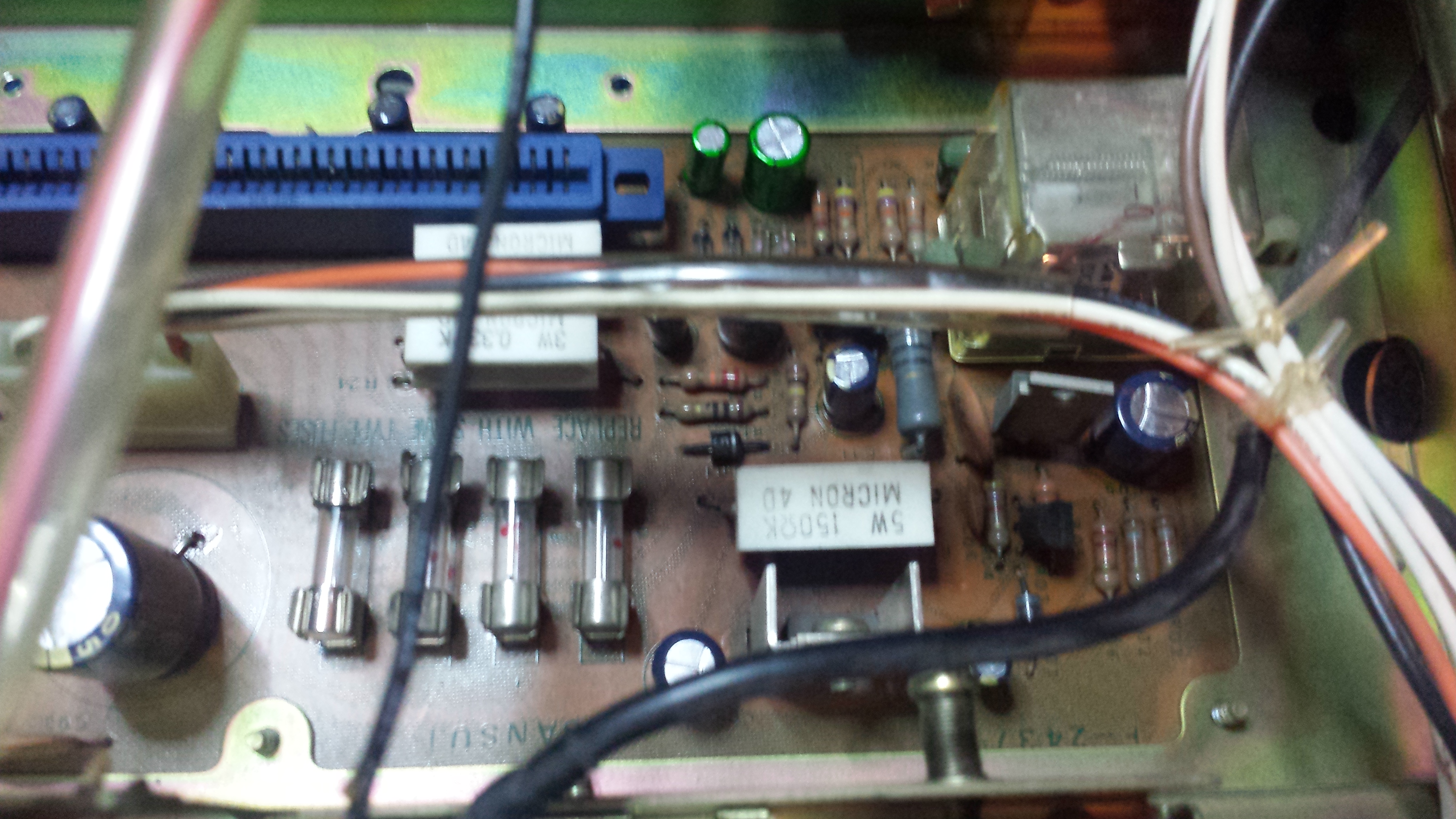
Power supply / protection board, sorry only have an after photo. There are two bipolar caps you can see they were replaced with (green) Nichicon ES series on the top middle of the board. These help power the transistors to drive the relay. Other electrolytics were replaced with Panasonic FC high temp high reliability capacitors. This board is used later as a test point for the amplifier alignment.
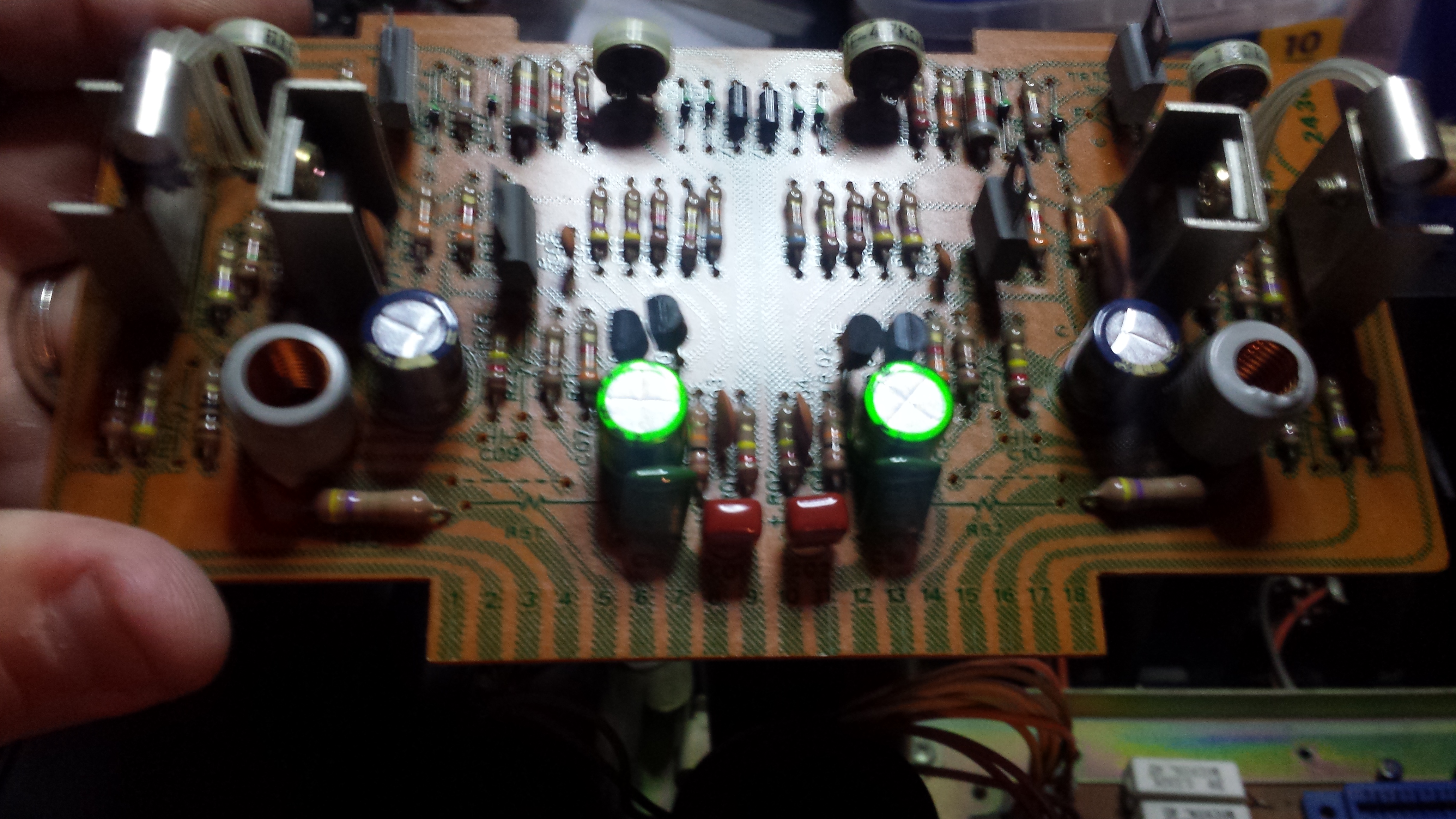
Amp board before Amp board after. 1uf caps in front replaced with stacked film caps, bipolar behind replaced with Nichicon ES, and filters replaced with Panasonic FC
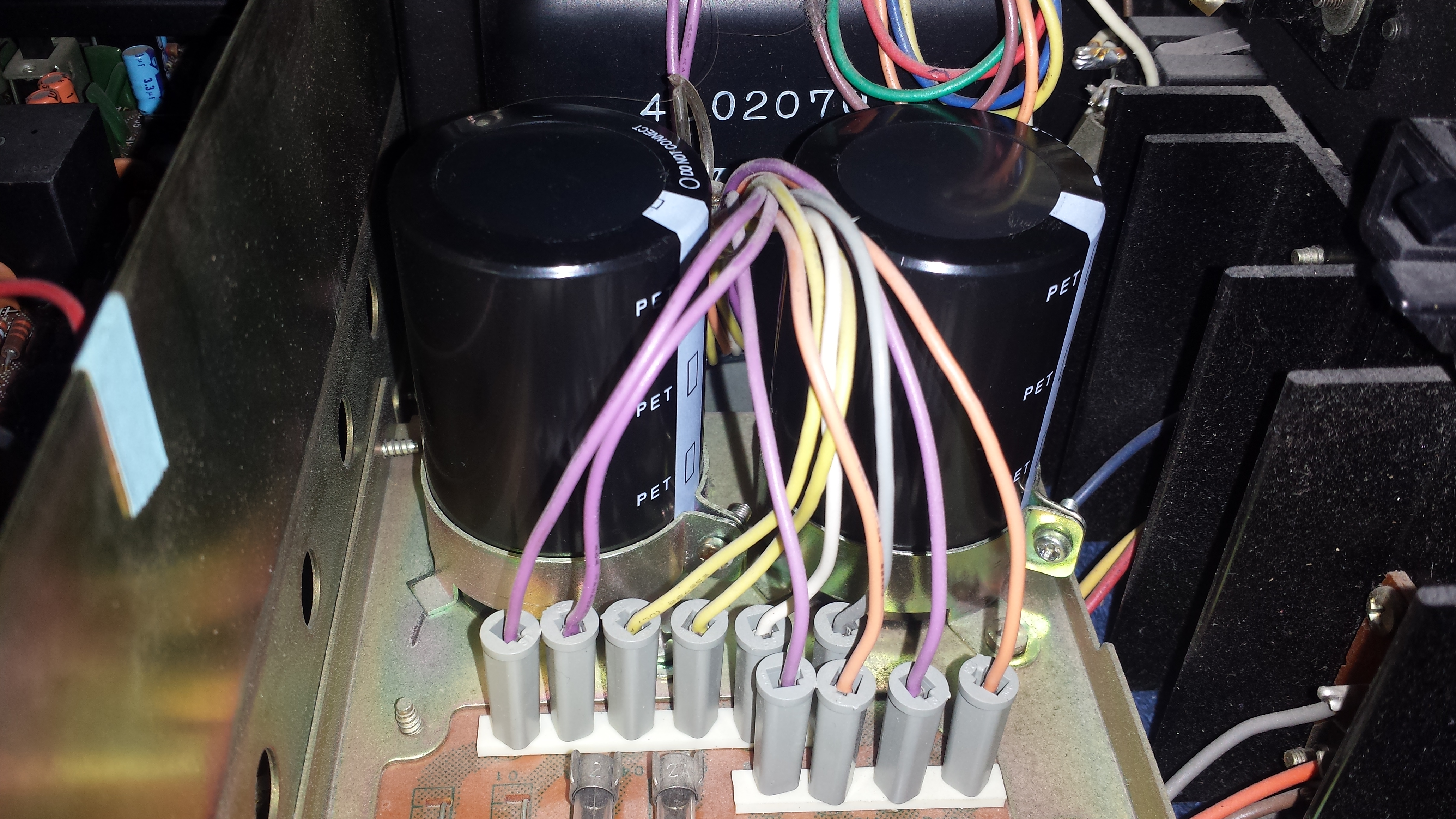
 New filter caps were installed. These are Panasonic THA 10000uf 80v which fit perfectly in the existing clamps.
 Next it was on to the phono preamp, sorry again no before picture.
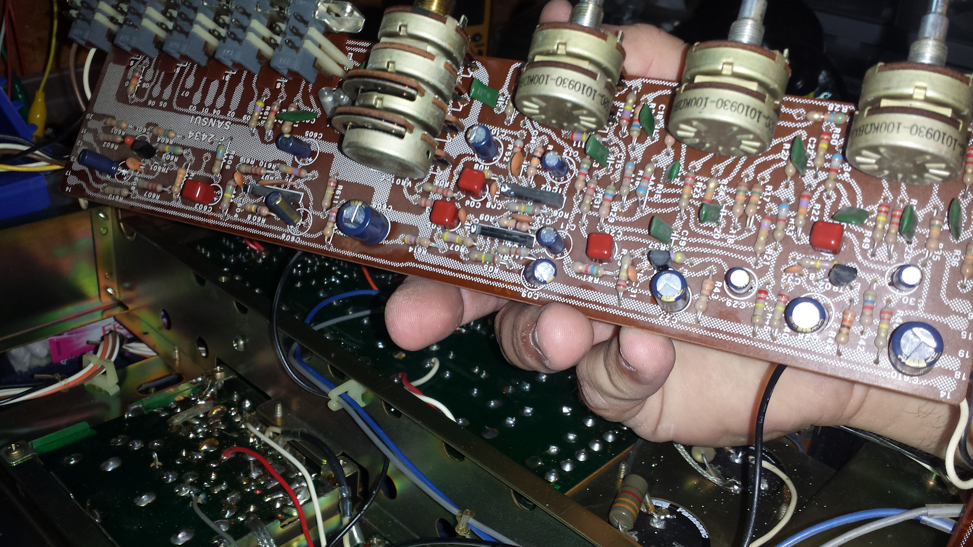
  Finally it was on to the preamp and EQ section. Some major disassembly required here but great results. All 1uf caps again replaced with stacked film caps. Before and after.
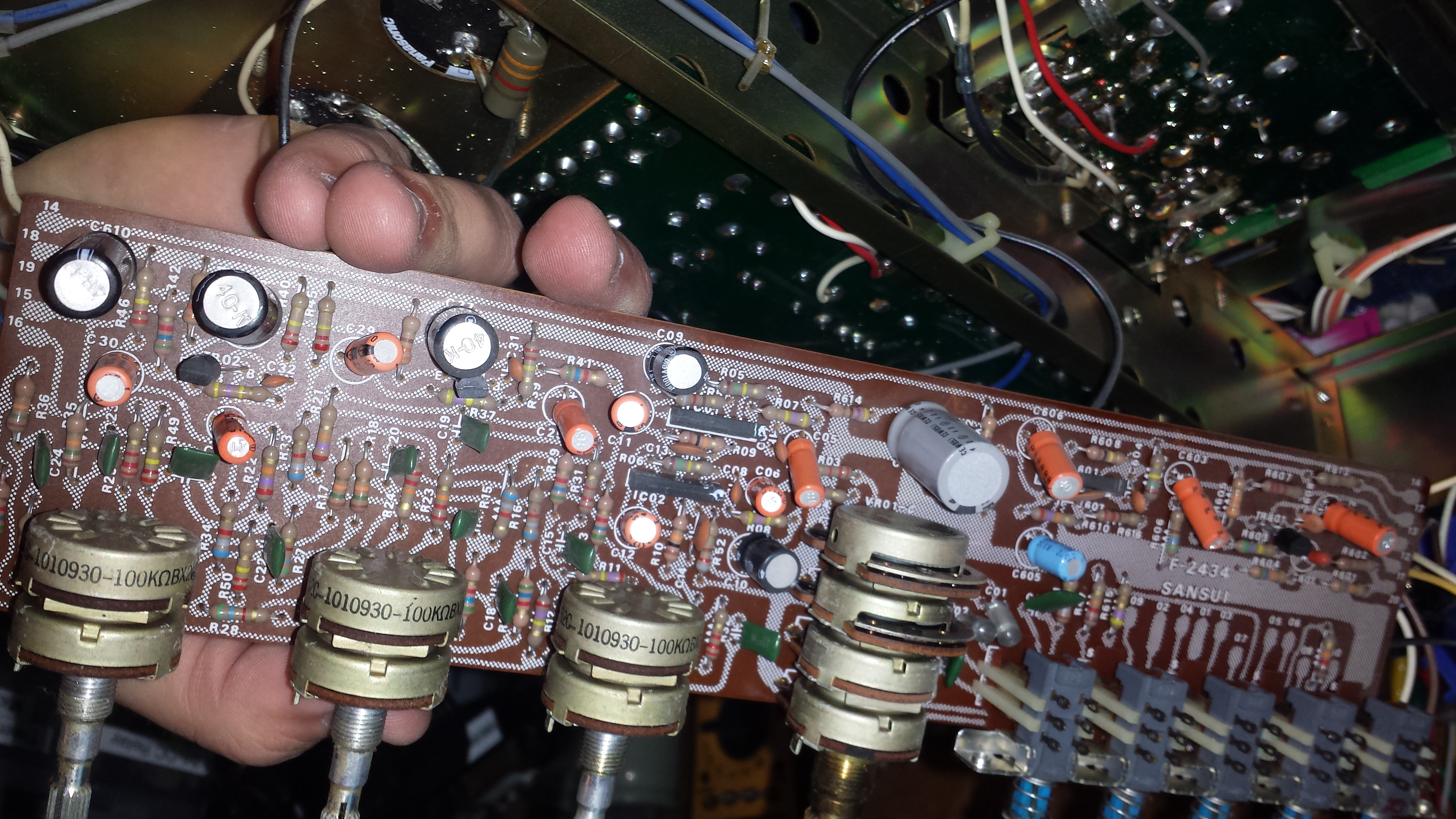
New LED lamps installed in dial diffuser. I found that it actually worked better to put the lamps in facing the diffuser. This gave a more uniform light across the dial and looks very much like the original incandescent.
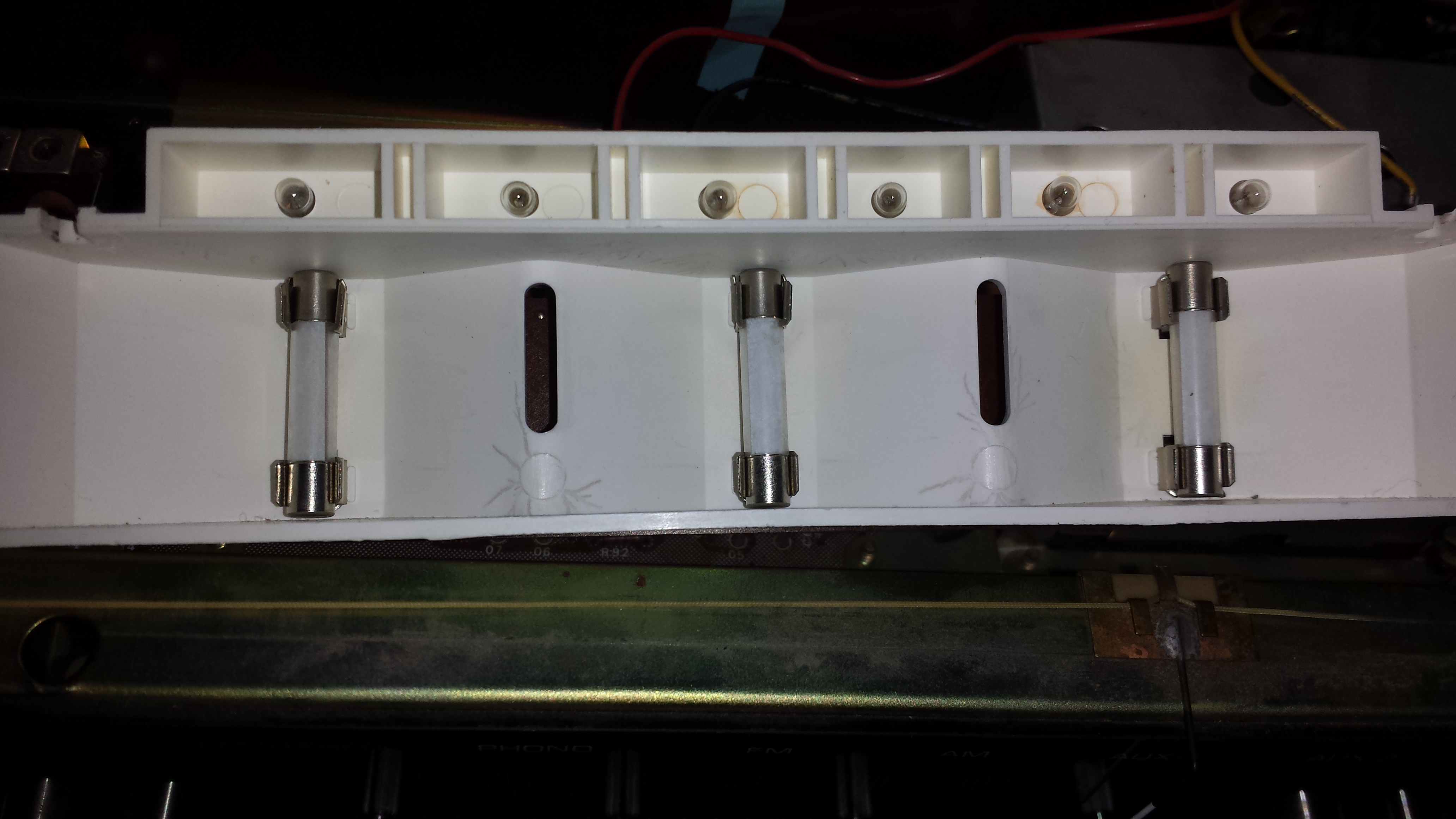
There is also a fuse lamp in each of the tuning meters. Again I installed the lamp to shine into the diffuser. This view is from the top of the meter looking down. Notice the yellowing of the white plastic which makes up the back of the meter. One big positive to LED conversion besides long life is the cool temperature which they run. If left as incandescent these housings would have yellowed badly and dimmed the meter.
Dial after the lighting replacement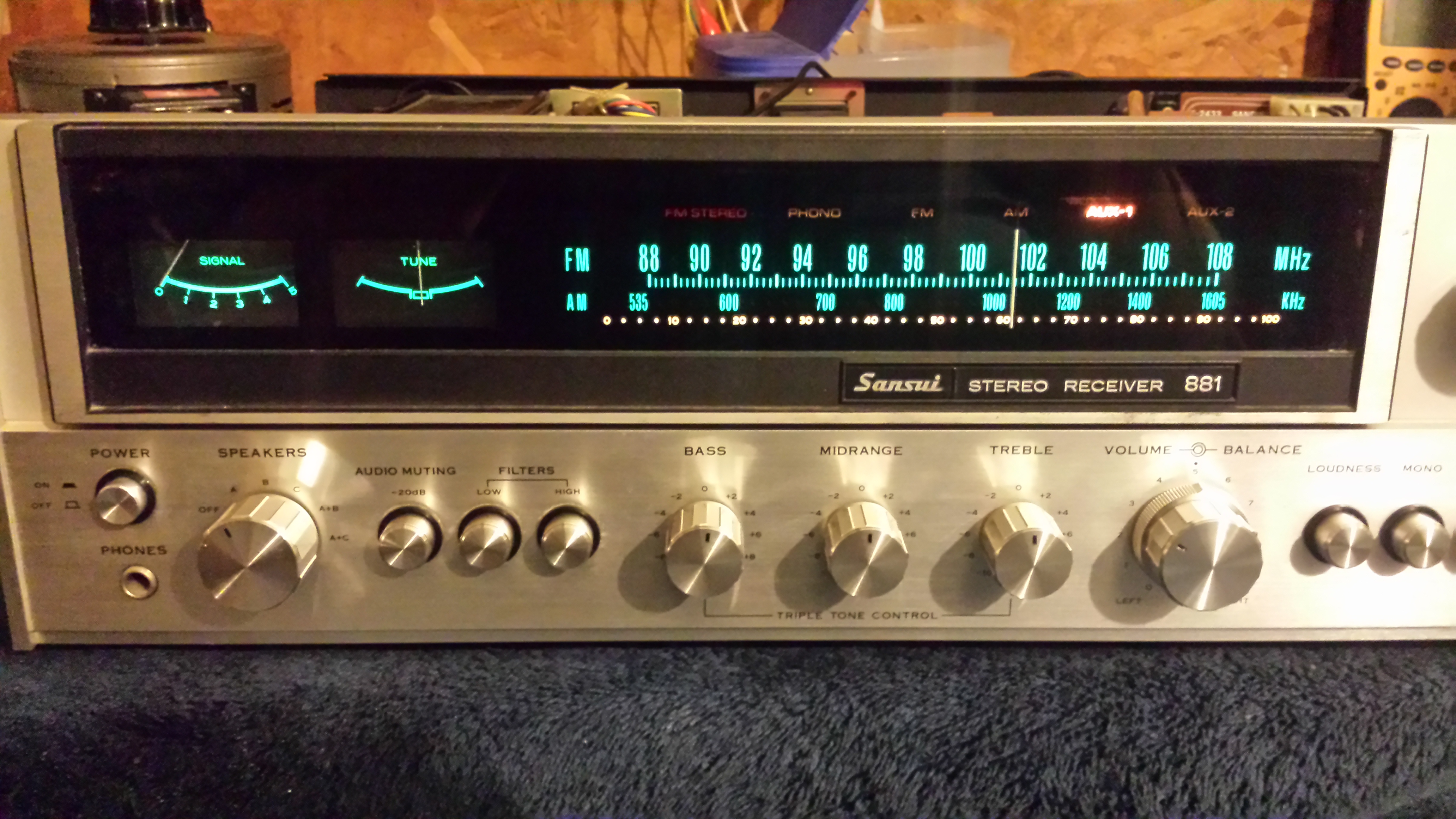 All cleaned up and ready for break in time.
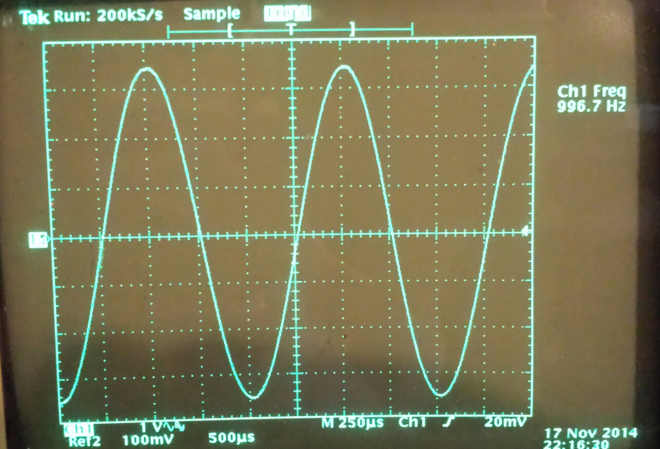
The amplifier was aligned and allowed to break in for several hours before rechecking bias and offset. A performance bench test was done and the amp was found to produce 74wpc@1kHz into an 8ohm load before clipping occured. Sansui rated this amplifer to produce 65wpc from 20Hz to 20kHz which when measured at several frequencies it has no trouble producing. Here is a shot of the scope with a 1kHz waveform being driven almost to clipping at 24.2v